Secure Digital Card Commands vary depending on the type of data bus protocol used. The SD Association, the organization in control of all Secure Digital Card Specifications, requires all SD card devices to support both the Serial Peripheral Interface (SPI) Bus and one-bit SD bus modes. The list below describes the 4 data bus protocols currently supported by Secure Digital memory cards.
The SPI bus solely supports a 3.3V power supply, does not require a host license.
Supported by all Secure Digital memory cards. Features separate command and data lines, and uses a proprietary data transfer format.
All SD memory cards support this bus mode, as well. In addition, UHS-I and UHS-II cards require this. Identical to the One-bit SD Bus Mode except it uses one command line and four data lines for accelerated data transfer speeds.
Uses two low-voltage differential signaling interfaces to transfer both commands and data. UHS-II memory cards include this interface along with the SD bus modes described above.
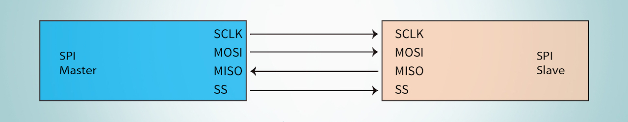
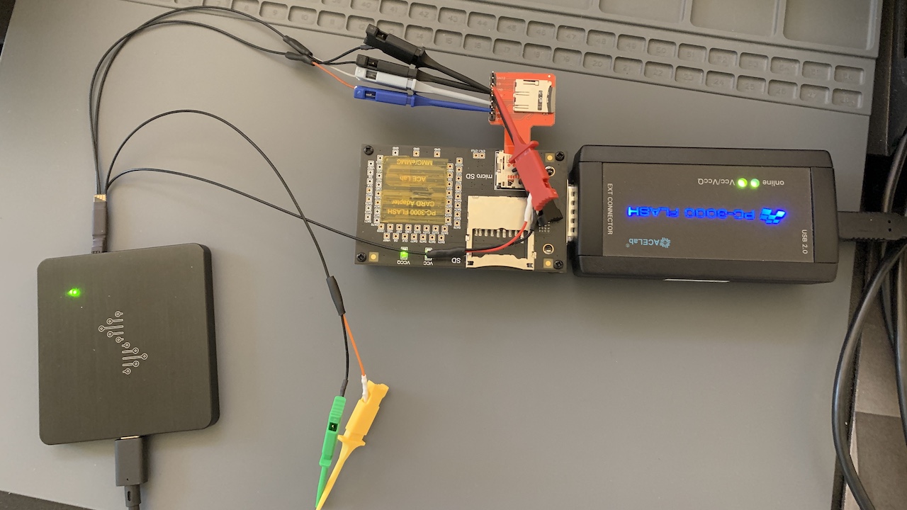
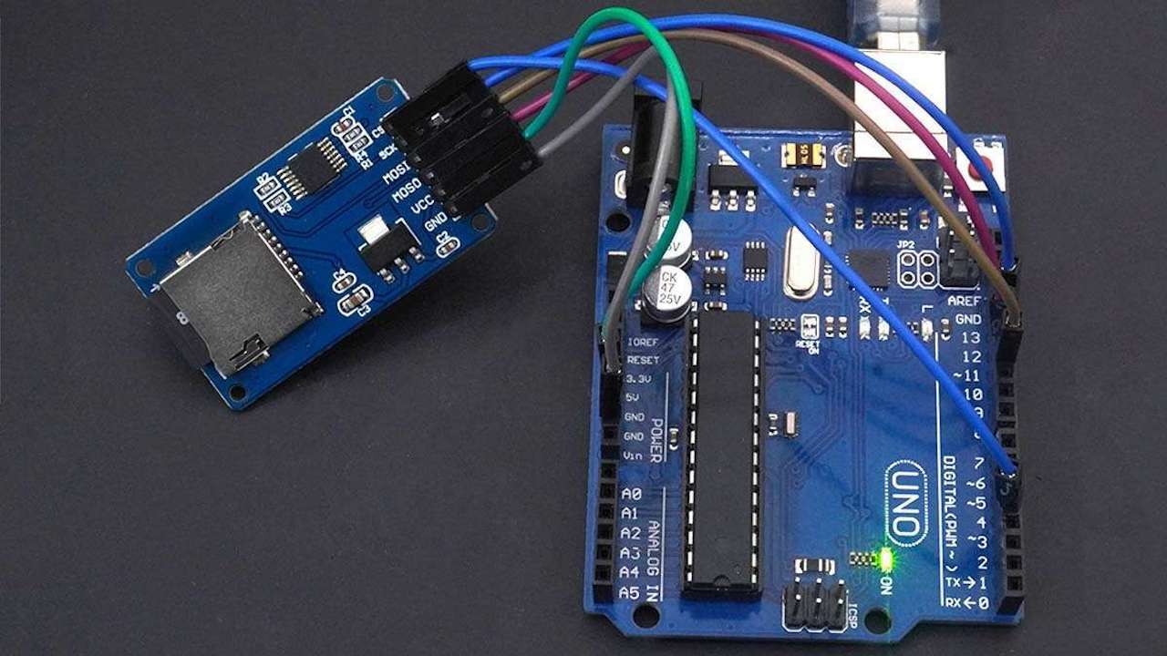
For communicating at the individual command level with SD memory cards, I recommend using the SPI Bus Protocol. Firstly, the SD Association mandates all SD memory cards support the the SPI bus protocol. Consequently, this one univeral protocol works with all Secure Digital memory. Secondly, being both open-source and non-proprietary, no one can ever restrict or prohibit use of the SPI Protocol. Thirdly, requiring only a 3.3V power line, a ground connection, a clock signal, and a MOSI-MISO line, one can implement the SPI Bus with just 4 connections.
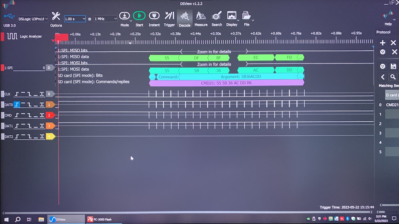
All Secure Digital Card Commands and data sent through the Serial Peripheral Interface Bus are 6 bytes, or 48 bits, long and are made of 8-bit, or 1 byte, words. Some transmissions may contain padding bits but the host and memory card always communicate using only multiples of 8 bits.
| Start Bit | TX Bit | CMD | ARG | CRC7 | End Bit | |
|---|---|---|---|---|---|---|
| Position | 47 | 46 | [45:40] | [39:8] | [7:1] | 0 |
| Width (bits) | 1 | 1 | 6 | 32 | 7 | 1 |
| Value | 0 | 1 | 1 |
The next four tables below list many of the SPI Protocol commands available to run. The list of supported commands in SPI mode consists of a subset of commands supported in SD mode. Set all padding bits to ‘0’.
Firstly, a table matching the Command ID with the Command Name appears. Secondly, a table displaying the Command ID with a Description of the Command. Thirdly, a table listing the Command ID, Command encoded in binary, and the contents of the command argument in bits. Lastly, a table showing the Command ID and the Format of the Response.
| CMD | Name |
|---|---|
| CMD0 | GO_IDLE_STATE |
| CMD1 | SEND_OP_COND |
| CMD6 | SWITCH_FUNC |
| CMD8 | SEND_IF_COND |
| CMD9 | SEND_CSD |
| CMD10 | SEND_CID |
| CMD12 | STOP_TRANSMISSION |
| CMD13 | SEND_STATUS |
| CMD16 | SET_BLOCKLEN |
| CMD17 | READ_SINGLE_BLOCK |
| CMD18 | READ_MULTIPLE_BLOCK |
| CMD24 | WRITE_BLOCK |
| CMD25 | WRITE_MULTIPLE_BLOCK |
| CMD27 | PROGRAM_CSD |
| CMD28 | SET_WRITE_PROT |
| CMD29 | CLR_WRITE_PROT |
| CMD30 | SEND_WRITE_PROT |
| CMD32 | ERASE_WR_BLK_START_ADDR |
| CMD33 | ERASE_WR_BLK_END_ADDR |
| CMD38 | ERASE |
| CMD42 | LOCK_UNLOCK |
| CMD55 | APP_CMD |
| CMD56 | GEN_CMD |
| CMD58 | READ_OCR |
| CMD59 | CRC_ON_OFF |
| CMD | Command Description |
|---|---|
| CMD0 | Resets the SD Memory Card. |
| CMD1 | Sends host capacity support information and activates the card’s initialization process. HCS is effective when card receives SEND_IF_COND command. Set all reserved bits to ‘0’. |
| CMD6 | Checks switchable function (mode 0) and switches card function (mode 1). |
| CMD8 | Sends SD Memory Card interface condition that includes Host Supply Voltage (VHS) information and asks the accessed card whether card can operate in supplied voltage range. Set all reserved bits to ‘0’. |
| CMD9 | Asks the selected card to send its card-specific data (CSD). |
| CMD10 | Asks the selected card to send its card identification (CID). |
| CMD12 | Forces the card to stop transmission in Multiple Block Read Operation. |
| CMD13 | Asks the selected card to send its status register. |
| CMD16 | Sets a block length (in bytes) for all following block commands (read and write) (note 2) of a Standard Capacity Card. Block length of the read and write commands are fixed to 512 bytes in SDHC and SDXC cards. The length of LOCK_UNLOCK command is set by this command in all cards, regardless of capacity. |
| CMD17 | Reads a block of the size selected by SET_BLOCKLEN command. |
| CMD18 | Continuously transfers data blocks from card to host until interrupted by a STOP_TRANSMISSION command. |
| CMD24 | Writes a block of the size selected by the SET_BLOCKLEN command. |
| CMD25 | Continuously writes blocks of data until ‘Stop Tran’ token is sent (instead of ‘Start Block’). |
| CMD27 | Programming of the programmable bits of the CSD. |
| CMD28 | If the card has write protection features, this command sets the write protection bit of the addressed group. The write protection properties appear in the card specific data (WP_GRP_SIZE). SDHC and SDXC cards do not support this command. |
| CMD29 | If the card has write protection features, this command clears the write protection bit of the addressed group. SDHC and SDXC cards do not support this command. |
| CMD30 | If the card has write protection features, this command asks the card to send the status of the write protection bits. SDHC and SDXC cards do not support this command. |
| CMD32 | Sets the address of the first write block to be erased. |
| CMD33 | Sets the address of the last write block of the continuous range to be erased. |
| CMD38 | Erases all previously selected write blocks. |
| CMD42 | Used to Set/Reset the Password or lock/unlock the card. A transferred data block includes all the command details. The size of the Data Block is defined with SET_BLOCK_LEN command. Reserved bits in the argument and in Lock Card Data Structure shall be set to 0. |
| CMD55 | Defines to the card that the next command is an application specific command rather than a standard command. |
| CMD56 | Used either to transfer a Data Block to the card or to get a Data Block from the card for general purpose/application specific commands. In case of Standard Capacity SD Memory Card, the size of the Data Block shall be defined with SET_BLOCK_LEN command. Block length of this command is fixed to 512-byte in SDHC and SDXC cards. |
| CMD58 | Reads the OCR register of a card. CCS bit is assigned to OCR[30]. |
| CMD59 | Turns the CRC option on or off. A ‘1’ turns the option on. A ‘0’ turns it off. |
| CMD | CMD in Binary | Argument |
|---|---|---|
| CMD0 | 000000 | [31:0] Stuff Bits |
| CMD1 | 000001 | [31] Reserved [30] HCS [29:0] Reserved |
| CMD6 | 000110 | [31] Mode (0 = Check function, 1 = Switch Function) [30:24] Set All Bits to ’0’ (Reserved) [23:20] All Set to ’0’ or 0xF (Reserved for Function Group 6) [19:16] Set All to ’0’ or 0xF (Reserved for Function Group 5) [15:12] All Set to ’0’ or 0xF (Reserved for Function Group 4) [11:8] Set All to ’0’ or 0xF (Reserved for Function Group 3) [7:4] Function Group 2 for Command System [3:0] Function Group 1 for Access Mode |
| CMD8 | 001000 | [31:12] Reserved Bits [11:8] Supply Voltage (VHS) [7:0] Check Pattern |
| CMD9 | 001001 | [31:0] Stuff Bits |
| CMD10 | 001010 | [31:0] Stuff Bits |
| CMD12 | 001100 | [31:0] Stuff Bits |
| CMD13 | 001101 | [31:0] Stuff Bits |
| CMD16 | 010000 | [31:0] Block Length |
| CMD17 | 010001 | [31:0] Data Address |
| CMD18 | 010010 | [31:0] Data Address |
| CMD24 | 011000 | [31:0] Data Address |
| CMD25 | 011001 | [31:0] Data Address |
| CMD27 | 011011 | [31:0] Stuff Bits |
| CMD28 | 011100 | [31:0] Data Address |
| CMD29 | 011101 | [31:0] Data Address |
| CMD30 | 011110 | [31:0] Write Protect Data Address |
| CMD32 | 100000 | [31:0] Data Address |
| CMD33 | 100001 | [31:0] Data Address |
| CMD38 | 100110 | [31:0] Stuff Bits |
| CMD42 | 101010 | [31:0] Reserved Bits (Set All to 0) |
| CMD55 | 110111 | [31:0] Stuff Bits |
| CMD56 | 111000 | [31:1] Stuff Bits [0] RD/WR |
| CMD58 | 111010 | [31:0] Stuff Bits |
| CMD59 | 111011 | [31:1] Stuff Bits [0] CRC option |
| CMD | Response Format |
|---|---|
| CMD0 | R1 |
| CMD1 | R1 |
| CMD6 | R1 |
| CMD8 | R7 |
| CMD9 | R1 |
| CMD10 | R1 |
| CMD12 | R1b |
| CMD13 | R2 |
| CMD16 | R1 |
| CMD17 | R1 |
| CMD18 | R1 |
| CMD24 | R1 |
| CMD25 | R1 |
| CMD27 | R1 |
| CMD28 | R1b |
| CMD29 | R1b |
| CMD30 | R1 |
| CMD32 | R1 |
| CMD33 | R1 |
| CMD38 | R1b |
| CMD42 | R1 |
| CMD55 | R1 |
| CMD56 | R1 |
| CMD58 | R3 |
| CMD59 | R1 |
The three tables below list most of the SPI Protocol application specific commands to run after executing CMD55. Firstly, a table matching the Command ID with the Command Name appears. Secondly, a table displaying the Command ID with a Description of the Command. Lastly, a table showing the Command ID, contents of the Arugment in bits, and the Format of the Response.
| CMD | Name |
|---|---|
| ACMD13 | SD_STATUS |
| ACMD22 | SEND_NUM_WR_BLOCKS |
| ACMD23 | SET_WR_BLK_ERASE_COUNT |
| ACMD41 | SD_SEND_OP_COND |
| ACMD42 | SET_CLR_CARD_DETECT |
| ACMD51 | SEND_SCR |
| ACMD18 | SECURE_READ_MULTI_BLOCK |
| ACMD25 | SECURE_WRITE_MULTI_BLOCK |
| ACMD26 | SECURE_WRITE_MKB |
| ACMD38 | SECURE_ERASE |
| ACMD43 | GET_MKB |
| ACMD44 | GET_MID |
| ACMD45 | SET_CER_RN1 |
| ACMD46 | SET_CER_RN2 |
| ACMD47 | SET_CER_RES2 |
| ACMD48 | GET_CER_RES1 |
| ACMD49 | CHANGE_SECURE_AREA |
| CMD | Description |
|---|---|
| ACMD13 | Transmit the contents of the card’s status register. The SD card (in SPI mode) responds with a R2 response. |
| ACMD22 | Send the numbers of the successfully written blocks (those without errors). Responds with 32-bit+CRC data block. |
| ACMD23 | Set the number of write blocks to be pre-erased before writing (to be used for faster Multiple Block WR command). ‘1’=default (one wr block). |
| ACMD41 | Transmit host capacity support information and activate the SD card’s initialization process. Set all reserved bits to ‘0’. |
| ACMD42 | Connect (‘1’) / Disconnect (‘0’) the 50 KOhm pull-up resistor on CS (pin 1) of the card. The controller may use the pull-up for card detection. |
| ACMD51 | Read the SD Configuration Register (SCR). |
| CMD | Response Format | Argument |
|---|---|---|
| ACMD13 | R2 | [31:0] Stuff Bits |
| ACMD22 | R1 | [31:0] Stuff Bits |
| ACMD23 | R1 | [31:23] Stuff Bits [22:0] # Blocks |
| ACMD41 | R1 | [31] Reserved [30] HCS [29:0] Reserved |
| ACMD42 | R1 | [31:1] Stuff Bits [0] set_cd |
| ACMD51 | R1 | [31:0] Stuff Bits |
Whenever a SD Card controller sends a command to a SD Card, the memory card always responds in one of five response formats.
The table below describes the 8 bits, or 1 byte, of data comprising the first command response format.
| Bit | Name | Description |
|---|---|---|
| 0 | In Idle State | The card is in idle state and running the initializing process. |
| 1 | Erase Reset | An erase sequence was cleared before executing because an out of erase sequence command was received. |
| 2 | Illegal Command | An illegal command code was detected. |
| 3 | CRC Error | The CRC check of the last command failed. |
| 4 | Erase Sequence Error | An error in the sequence of erase commands occurred. |
| 5 | Address Error | A misaligned address that did not match the block length was used in the command. |
| 6 | Parameter Error | The command’s arguments (e.g. address, block length) reside outside the allowed range for this card. |
| 7 | MSB | Always Zero |
The second response format sends a busy signal. The first byte transmits the R1 Command Response and then adds extra ‘0’ bytes afterwards. An idle SD card signals to the controller availablity to receive another command by sending a non-zero byte of data.
The third response format is 2 bytes in length, with the first byte being identical to SD Card Command Response Format 1 and the second byte described in the table below.
| Bit | Name | Description |
|---|---|---|
| 0 | Card Locked | Set to ‘1’ when locked. Reset to ‘0’ when unlocked. |
| 1 | Write Protect Erase Skip Lock/Unlock Failed | Set when the host attempts to erase a write-protected sector or makes a sequence or password errors during card locking and unlocking. |
| 2 | Error | A general or unknown error occurred during the operation. |
| 3 | CC Error | Internal card controller error occurred during the operation. |
| 4 | Card ECC Failed | Card internal ECC applied successfully but failed to correct the data. |
| 5 | Write Protect Violation | The command attempted to write a write-protected block. |
| 6 | Erase Parameter | An invalid selection for erase sectors or groups. |
| 7 | Out of Range CSD Overwrite | A parameter out of range error occurred during the operation. |
The fourth response format is 5 bytes, or 40 bits, long. The first byte sent is identical to Response Format 1. The remaining 4 bytes, or 32 bits, contain the contents of the OCR register.
At 5 bytes, or 40 bits, in length, Response Format 5 results when a SD Card responds with the SEND_IF_COND command (CMD8).
To conclude, I recommend learning and using the Serial Peripheral Interface Bus Protocol for direct, command-level communication with Secure Digital Flash Memory Cards. Firstly, all SD cards support the SPI protocol. Secondly, being an open-source, non-proprietary format makes the protocol free to use for everybody. Thirdly, SPI communications only require 4 connections: power, ground, a clock signal, and a singe duplex MOSI-MISO line, making them simple to physically implement.